Baluns for OCFD Antennas
It's the Balun, Stupid !
(said with tongue in cheek)
During this Field Test, 12 different BALUNs were tested.
Below you will see 5 of the 12 BALUNs tested.
These 5 pretty much sum up what I learned.
B0: No BALUN at all:
Many will be curious as to why I even tested this. Well, I wanted to know exactly what happens and testing it was the only way that I knew of to find out.
As you see, the curve is very jagged. SWRmin was at 3.370 MHz, but I could not find any frequency within the range scanned where J0 occurred.
B1: 1:1 Guanella (Choke) BALUN:
This is a special Teflon-Insulated coax, the size of RG-58, but much more flexible than RG-142.
17 turns were cross-wound onto an FT-240-43.
It may be assumed that the frequency at which SWRmin occurred is fairly accurate. After all, this is a straight forward W1JR current BALUN.
B4: DJ0IP 4:1 Hybrid BALUN
This BALUN is my own design. It was developed by testing several different number of turns on several different ferrite mix Toroids for each of the two BALUNs. The Guanella is on an FT-240-43; the Ruthroff is on an FT-240-61.
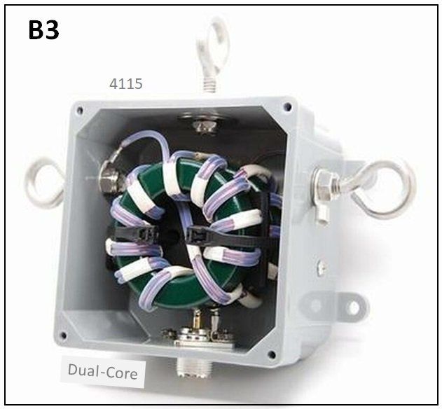
B3: A Commercial 4:1 Guanella BALUN
This popular commercial BALUN is promoted for use with OCFD antennas. :-(
Although it is a properly built Dual-Core BALUN, its two Toroids are of the wrong ferrite mix. They have (by far) insufficient permeability for this task. In addition, they have too few turns of transmission line on each core.
As a result, the Common Mode Impedance of this BALUN falls short of what it should be . . . BY A COUNTRY MILE !
As you will see, this is a LOUSY BALUN
for use in OCFD antennas.
However, it is perfectly OK for use in many
other antennas having less Common
Mode Current than OCFD antenna.
- - - - - - - - - - - - - -
I was unable to locate a resonant frequency (j0), and SWRmin is about 350 kHz higher than the actual frequency it should be at.
THIS IS CAUSED BY COMMON MODE
CURRENT ON THE FEEDLINE.
Adding a 1:1 Maxwell choke to the BALUN dropped SWRmin to 3.570 MHz - still WAY too high in frequency.
Replacing the Maxwell choke with a 1:1 Guanella choke dropped SWRmin to 3.440 MHz. PERFECT.
The Guanella choke has about 8k Ohms of CMI (measured) on 80m.
BOTTOM LINE: This commercial "OCF" (?) BALUN does not even come close to being adequate for use in an OCFD antenna! SHAME on "XYZ" !
Most people associate Common Mode Current (CMC) with a radiating coax. Some also realize that it causes distortion of the pattern of radiation. This is correct, but not the full story.
OTHER RESULTS OF CMC on the Feedline: An explanation follows at the bottom of this page.
When testing this commercial BALUN, as will as all other BALUNs, we watched closely for the things listed below. With this BALUN, many of these negative aspects were seen. SHAME SHAME SHAME !
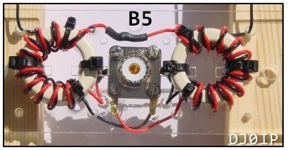
B5: DJ0IP 4:1 Guanella BALUN:
The Toroids used in this home-brew 4:1 Guanella BALUN have significantly higher permeability than those used in the commercial 4:1 Guanella tested (B3).
However, again the turns count is too low. This BALUN needs about 50% more turns to obtain the amount of Common Mode Impedance required for the task. This is not possible on these small cores.
The BOTTOM LINE: A 4:1 Guanella BALUN is inadequate for use (alone) in an OCFD BALUN unless a much gentler feedpoint split (i.e. 40%) is used. Although 40% works fine on a 40m OCFD, it is not ideal for an 80m OCFD.
The solution is to add an RF Choke to the BALUN.
(See text on the right.)
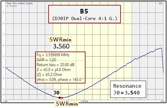
With this home-brew 4:1 Guanella BALUN, things look a LOT better than with the commercial BALUN. Resonance (j0) is about 20 kHz below SWRmin, which is at 3.560 MHz.
Never-the-less, this is still about 100 kHz too high! REASON: There is residual Common Mode Current (CMC) on the feedline. An additional choke is required to fully remove the CMC.
The addition of a 1:1 Maxwell choke with about 1k Ohms of CMI dropped SWRmin 60 kHz, to 3.500 MHz; better, but still not where it should be.
Replacing the Maxwell with a 1:1 Guanella choke dropped SWRmin to 3.460 MHz. PERFECT.
Actually, the Guanella Choke was overkill. A second Maxwell choke probably would have been sufficient, but I only had one Maxwell choke with me at the time.
4:1 Guanella BALUNs:
When I conducted my Common Mode Current Field Test on 40m OCFD antennas in 2013, I concluded that a good (Dual-Core) 4:1 Guanella BALUN was sufficient for use in OCFD antennas.
NOW, it was clearly insufficient! What had changed?
Both antennas were at approximately the same height (40m: 11m high; 80m: 12m high).
Since the electrical height of the 80m OCFD was only half as high as that of the 40m OCFD, I assumed the difference was due to electrical height. But Tom Rauch (W8JI) kept insisting that height has nothing to do with it. I did not agree. I was wrong! Tom was right!
THE POSITION OF THE FEEDPOINT HAD CHANGED!
I had used a feedpoint position of about 40.5% from the end of the antenna on my 40m OCFD, whereas the feedpoint position on my 80m OCFD was 29.7%. OBVIOUSLY, moving the feedpoint 10% closer to the end of the antenna had caused a substantial increase in Common Mode Current!
The amount of Common Mode Current on an OCFD antenna is highly
dependent on the distance of its feedpoint from the center of the antenna.
The closer to the end of the antenna, the higher the CMC!
Negative Effects of Common Mode Current on the Feedline
Here's what really happens:
When RF flows on the outer surface of the coax, the coax has effectively become part of the antenna. This not only changes the overall length of the antenna, it also modifies its configuration.
As a result of this change in length, the antenna resonance also changes. Most people confuse "resonance" with the frequency at which the minimum SWR occurs (call it "SWRmin"). This of course is wrong; resonance and SWRmin are two different things. However, SWRmin also changes when CMC is flowing on the coax.
Other negative effects of CMC on the coax:
- The entire coax radiates RF power, which may cause all sorts of problems with the consumer products in your house or the neighbor's house.
- CMC on the coax may increase the noise level on the Receiver.
- You get bogus readings on an antenna analyzer.
- The frequency of SWRmin skews up the band (on the fundamental band).
- Normally it only skews on the fundamental band, not on the higher harmonic bands. This is because the level of CMC is a magnitude greater on the fundamental band than on the harmonic bands. (Source: DJ0IP's 2013 CMC Test)
- The shape of the SWR curve across the band begins to flatten with CMC, and its dip broadens out when the CMC increases.
- This is one reason why many people believe the bandwidth of the OCFD is much broader than that of a common dipole!
- Worst case, with lots of CMC on the coax, it may cause a double-dip in SWR.
- When measuring the SWR and other parameters, if you touch the coax connector with your hand, the reading on the analyzer changes.
- This is also why you often see a different reading on the analyzer than on the station SWR meter (when connected to the station, there is a path to ground).
- The level of SWR and other characteristics change noticeably with small changes in the length of coax between the transmitter and the antenna
- This is why some OCFD Antenna manufacturers specify certain lengths of coax to use, or lengths to avoid.
- AND THIS was clearly happening when we tested the commercial 4:1 Guanella BALUN (B3).
[END]


