END-CONNECTED OFF-CENTER-FED DIPOLE
WHAT IS IT.?
An ECOCFD is a hybrid between:
- an Off-Center-Fed-Dipole (OCFD) and
- an End-Fed-Half-Wavelength (EFHW) antenna.
Specifically, it is an OCFD antenna, fed usually about 17 to 20% from one end (therefore "OCFD"), but the shield of part of the coax is used as the short-end of the OCFD antenna radiator. It is terminated by a 1:1 Guanella choke-balun. Thus, the shield radiates between the actual feedpoint and the Guanella choke. The other leg of the OCFD is normal wire.
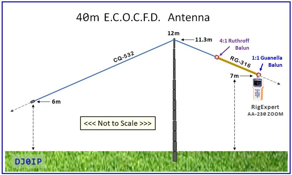
Example: 40m ECOCFD:

In this build, the coax stub for connecting to the antenna is only about 10 cm (4 in.) long. You can extend it to the shack with any length of 50 Ohm coax.
In order to have the frequency of minimum SWR inside of the harmonic bands, it is necessary to trim the overall length such that minimum SWR on 40m is below the band. The capacitor in the middle raises the resonance of the antenna on 40m, without changing resonance on higher bands.
Not shown but absolutely necessary: a high Ohm (a few Meg Ohms) 3 Watt bleeder resistor across the capacitor to protect it from static electricity.
The advantage of this antenna over an EFHW antenna is, it moves the feedpoint farther away from the shack, thus reducing the feedpoint impedance to near 200 Ohms and reducing the amount of Common Mode Current at the feedpoint.
The shield of the coax begins radiating at the feedpoint's 4:1 Ruthroff UNUN and radiation is terminated at the 1:1 Guanella (choke) BALUN. The coax between the Guanella BALUN and the shack does not radiate.
Photo Gallery:

The TX36/23/15/4A11 Toroid is strapped to an FR4 (epoxy board) backplane. The L-Adaptor and the insulator are optional, for use when erected as an Inv.-V antenna. When erected as an Inv.-L they are not required. (Ferrite similar to #43).
For my initial testing, I erected the ECOCFD an an Inverted-V, so that I could compare its SWR and performance to my standard 40m OCFD. The shape an heights shown in the drawing on the right is fairly close to that of my 404-UL OCFD.
Note: although the antenna analyzer is directly connected to the 1:1 Guanella BALUN, that is NOT the feedpont. The antenna's feedpoint is at the 4:1 Ruthroff UNUN about 13 ft. (3.8m) away from the analyzer. Thus, the analyzer's readings do not reflect the exact impedances at the feedpoint.
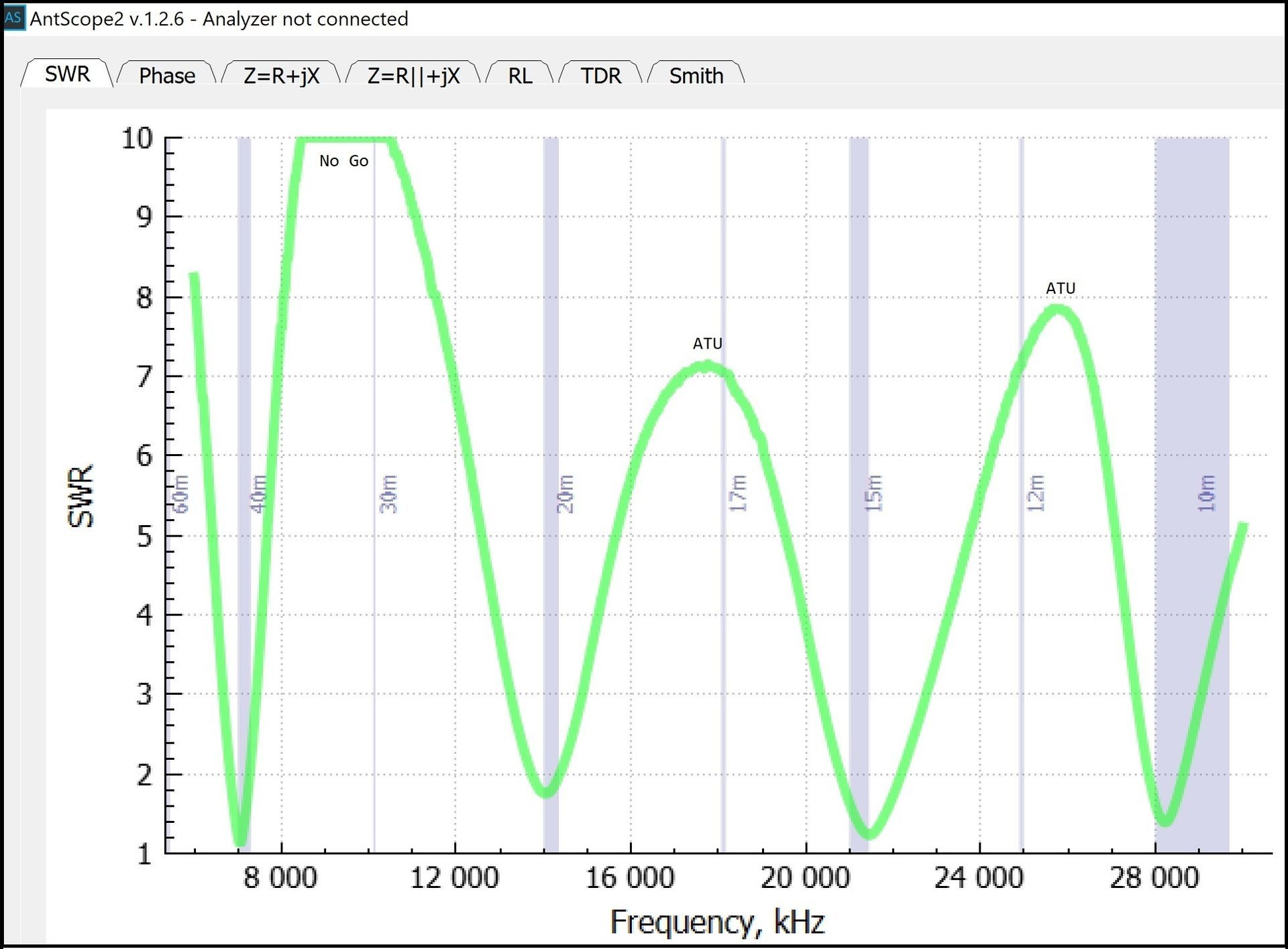
The graph on the right shows the SWR curves across the HF spectrum.
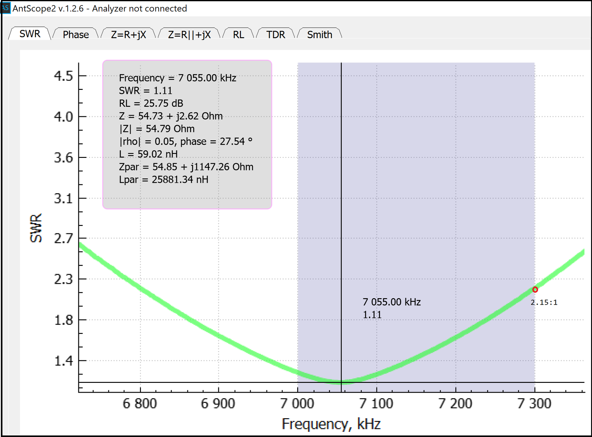
The SWR on the classic HF bands is excellent, but not on the WARC bands.
- 17m & 12m are useable with an Antenna Tuner
- 30m SWR is very high; if used with a Tuner, performance will be lower than on the other bands.

The 4:1 Ruthroff (voltage) UNUN has 2 turns of twisted pair transmission line wrapped through a pair of BN43-7051 Binocular Ferrite cores.
Its efficiency is 99%.


Dimensions are in meters.
The value of the capacitor will vary depending on where you want resonance to be.

OTHER CONFIGURATIONS:
INVERTED-L:

I was unable to measure the ECOCFD in this configuration because I am currently unable to erect a second pole to support the end.
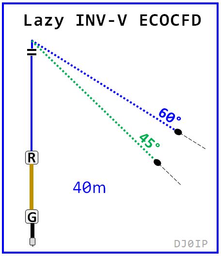
LAZY INVERTED-L / LAZY INVERTED-V

I tested the antenna in both configurations; 60 deg. had the best results. The results and more info are posted: HERE
Like with any Inv-L antenna, the lengths of the vertical and horizontal segments may be adjusted to adapt to the height of your pole/support.
In a nutshell, these two configurations need only half the space of a horizontal dipole and deliver about the same performance.
Just for fun, see what happened the first time I went to the field to test this:
NEXT PAGE: First Day in the Field Testing


