DG0SA Choke-Balun

DG0SA + SRG Hybrid Balun

The DG0SA Choke-Balun is touted by many to be an excellent choke-balun.  This (false) claim is based on S21 lab measurements using a 200 Ohm purely-resistive load!

As we will seen in these field tests of the antenna, this choke-balun has problems with Common Mode Current.  This results in a dramatic skewing of resonance and distortion of the SWR curve on some bands.

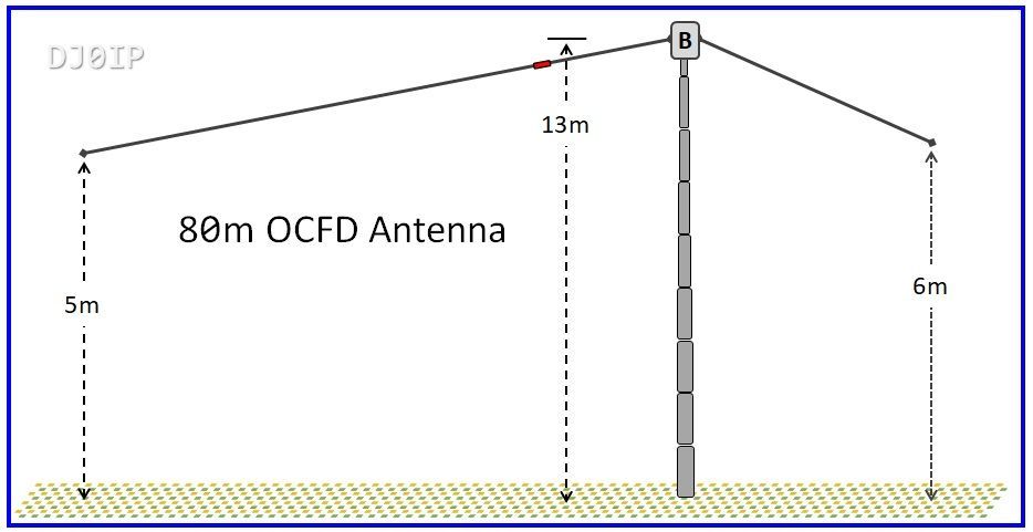
In the 80m OCFD antenna used for testing these Hybrid baluns, the DG0SA has about 4k Ohm less than is need (minimum) to impede the Common Mode Current generated by this antenna.

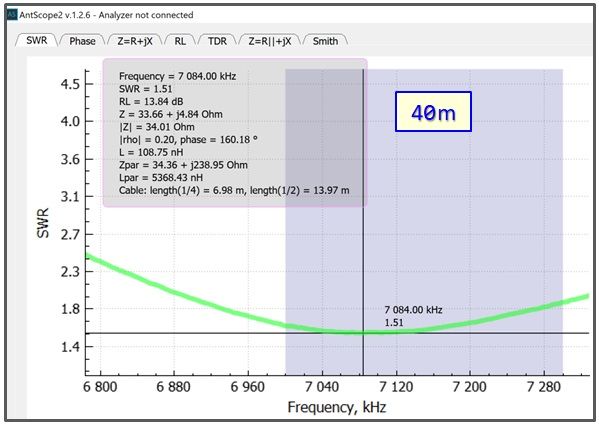
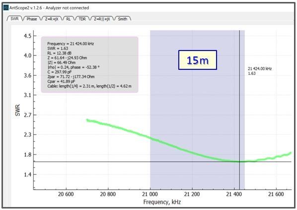
SWR SCANS:

Most readers will probably think the SWR band scans look pretty good.  NOT ME!

I was very disappointed in the results.  You will see exactly why in the next set of band scans.

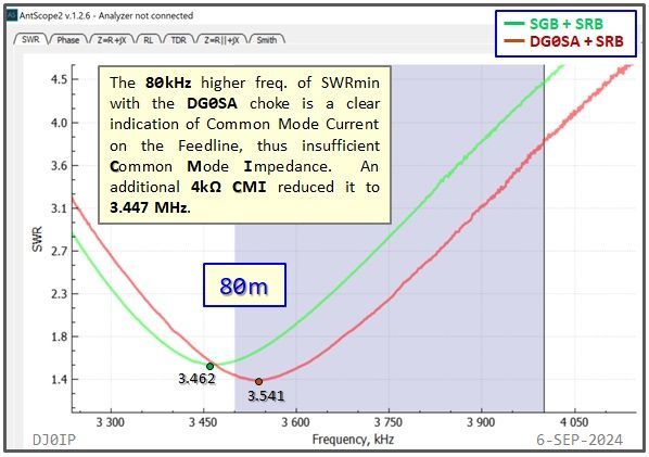
COMPARING to my standard Hybrid Balun (SGB + SRB) which has the same 4:1 Ruthroff (SRB) + a normal 1:1 Guanella choke balun (SGB):

Though not apparent to most readers, the 80m OCFD with the DG0SA choke-balun has significant Common Mode Current Problems. 

I did a quick test to see just how much more Common Mode Impedance was required to eliminate the Common Mode Current.  One of the things Common Mode Impedance does to the antenna is skew the frequency of minimum SWR (
SWRmin) up in frequency.

In this case it skewed SWRmin up the band about 80 kHz.

From the measurements made with my standard Hybrid Balun (SGB + SRB), I know that SWRmin must occur at
about 3.450 MHz.

In order to determine how much more Common Mode Impedance (CMI) the DG0SA choke required, I added several Maxwell Chokes one at a time and measured the frequency of minimum SWR.


Each choke has a CMI of about 1k Ohms.  As can be seen from the chart, each choke resulted in a reduction of SWRmin up to the 4th choke.


When I added the 5th choke, no further reduction in SWRmin occurred.   

The sweet spot is 4 chokes, or and additional 4k Ohms of Common Mode Impedance.


DOWNLOADS:


The exact details of each of these measurements may be examined using the freeware software "AntScope-2".


If you prefer a different software, you can download the .s1p or the .csv files of these measurements.

I prefer the AntScope-2 software and recommend you use this program if you want to discuss this with me.


AntScope-2 is a freeware available for Windows, MacOS, & Linux on the RigExpert web site:


Win: https://rigexpert.com/files/software/Antscope/antscope2forwindows/


MacOS: https://rigexpert.com/files/software/Antscope/antscope2formacos/


Linux: https://rigexpert.com/files/software/Antscope/antscope2forlinux/


.asd files for AntScope-2 .s1p files for other Apps .csv files for other Apps

NOTE: Each of these downloads contains a zipped file. You must unzip the files to retrieve the individual data files.


DISCUSSION AND CONCLUSION


I don't understand what many people find so attractive on this DG0SA choke.   As Toroid-based chokes go, it is lousy.  Its performance rivals that of a Maxwell choke, but it is clearly inferior to a good Toroid choke.

It seems to me people enjoy being deceived.   Keep in mind:


  • Inductors (and chokes) increase in inductance by the square of the number of turns.


  • With two inductors (chokes) on a shared core, each inductor has only half of the available space to wind its transmission line onto.  This results in half as many turns and only 1/4 as much inductance.


  • Then when we wire the two chokes in parallel, it halves the inductance again, resulting in only 1/8 as much inductance as we could get with a single choke having twice as many turns as each of the two transmission lines on this choke.


Obviously, it is much easier to wind a single transmission line in one direction onto a core than winding two separate transmission lines and wiring them in parallel.   

WHY BURDEN YOURSELF WITH EXTRA (USELESS) WORK?


CONCLUSION:


I see no reason to use this design in any application.


ADDITIONAL INFORMATION:


The field work used to evaluate this choke was done in 3 field tests:

  1. Common Mode Current Field Test (2013 - on a 40m dipole)
  2. Repeat of the 2015 Battle of Baluns Test (on an 80m OCFD)
  3. Step-by-step CMI appraisal in 1k Ohm increments, using the system I developed in 2015.


You can read more details on these on this page:

DG0SA "DUAL - TRANSMISSION LINE" CHOKE-BALUN


NOTE: Throughout this section of my web, whenever I state the value of the Common Mode Impedance of chokes or balun, it is based on the values shown in the color charts by Steve Hunt, G3TXQ (SK), published on his web, here: G3TXQ: RF-Chokes


DISCLAIMER:

I have reported my measured results here.  I am not an expert on Toroid technology, and welcome ALL feedback, whether supporting or disproving my own results.


Share by: