
DG0SA "DUAL - TRANSMISSION LINE" CHOKE-BALUN
This 1:1 Current Balun was designed by Wolfgang Wippermann, DG0SA (SK), in November of 2012. It is claimed to have high Common Mode Impedance (CMI) over a broad frequency range.
It consists of two 100 Ohm transmission lines, each with 12 Bifilar turns wound onto a Wuerth Toroid. The two transmission lines are connecting in parallel, creating a choke balun with 50 Ohm impedance on its input and output.
This balun came in 3 sizes:
- Large, wound with 12 turns of PTFE-insulated, AWG-18 wire, onto a Wuerth "RK4" Toroid (60mm dia.)
- Medium, wound with 12 turns of PTFE-insulated, AWG-20 wire, onto a Wuerth "RK3" Toroid (40mm dia.)
- Small, wound with 12 turns of "LFL" wire (East-German Army Field Phone wire), AWG-30, onto a Wuerth "RK3" Toroid (40mm dia.)
Rather than build my own from his kit, I purchased an assembled small version directly from Wolfgang in 2012 to use in my Field Tests. I wanted to be certain the balun was wound correctly.
I chose the small version because it is similar in size to the FT-140-43.
Before using it, I coated the choke-balun with black Liquid Electrical Tape for insulation. It is really only necessary to insulate the electrical connections, but I coated the entire balun.


A Closer Look at the DG0SA, Compared to a Standard 1:1 Guanella:

The chart above compares the two different designs. Both use the Guanella design. The DG0SA has two Guanella chokes on it, one on the left half, the other on the right half of the Toroid. When we connect the two chokes in parallel, the resulting CMI is only half as much as the CMI of each choke by itself.

My First Encounter with the DG0SA Choke-Balun:
Everyone knows that Common Mode Current causes the coax to radiate, which can cause RFI in the shack and affect consumer devices in the house. I wanted to learn what else it does.
- How much Common Mode Current does it take on the transmission line in order to actually see some kind of negative effect on the antenna characteristics?
- What happens when the Common Mode Current increases?
- How much Common Mode Impedance does it take to completely remove all of the Common Mode Current, or at least get it below the level where it begins to do harm?
To find the answers to some of these questions, I conducted an extensive Field Test in 2013 to learn/understand how Common Mode Current affects antennas.
I developed a suite of tests and ran them first on a 40m dipole with two different choke-baluns, then on a 40m OCFD antenna with two different choke baluns.
You can read all about my Common Mode Current Test (CMC TEST) on my other web site, here:
https://www.dj0ip.de/cmc-test/
I began by testing the 40m dipole. I tested it first with a W2DU (Maxwell) 1:1 choke-balun, and then with the DG0SA choke balun. I tested several configurations (see full description in the actual CMC TEST at the link above).
Fundamentally, the test consisted of testing with different lengths of coax, with and without ground, and then testing at the "Worst Case", which is a physical full wavelength of coax, skewed radically to one side, such that it is directly under one side of the antenna.
For each configuration I scanned the 40m band with a scanning analyzer and saved the scan, then applied a 100 Watt carrier to the antenna and measured the actual Common Mode Current (in mA) at each of the pre-defined measurement points. When testing the OCFD, I also repeated all tests on 20, 15, & 10m bands.
For each configuration I scanned the band using a RigExpert AA-54 scanning analyzer and saved the scan, then applied a 100 Watt carrier to the antenna and measured the actual amount of Common Mode Current (in mA) on the coax at each of the pre-defined measurement points.
By comparing the amount of the Common Mode Current to the shape of the SWR curve, I could see how various amounts of current affected the shape of the curve.

I ran 16 different tests on the antenna with each of the two baluns. The first 12 tests had the coax running perpendicularly (90 degrees) away from the antenna.
The final 4 tests were conducted with the coax skewed radically to one side as shown in the drawing above.
Then I rotated the antenna 180 degrees and repeated all tests.
The results of my measurements are shown in the table on the right.
At the end of 3 weeks of testing and approximately 1000 measurements, I determined the critical point of Common Mode Current Mode Current to be 30mA. Above 30mA I could just barely begin to see a skewing (flattening) of the SWR curve. It became quite apparent at about 50 mA.
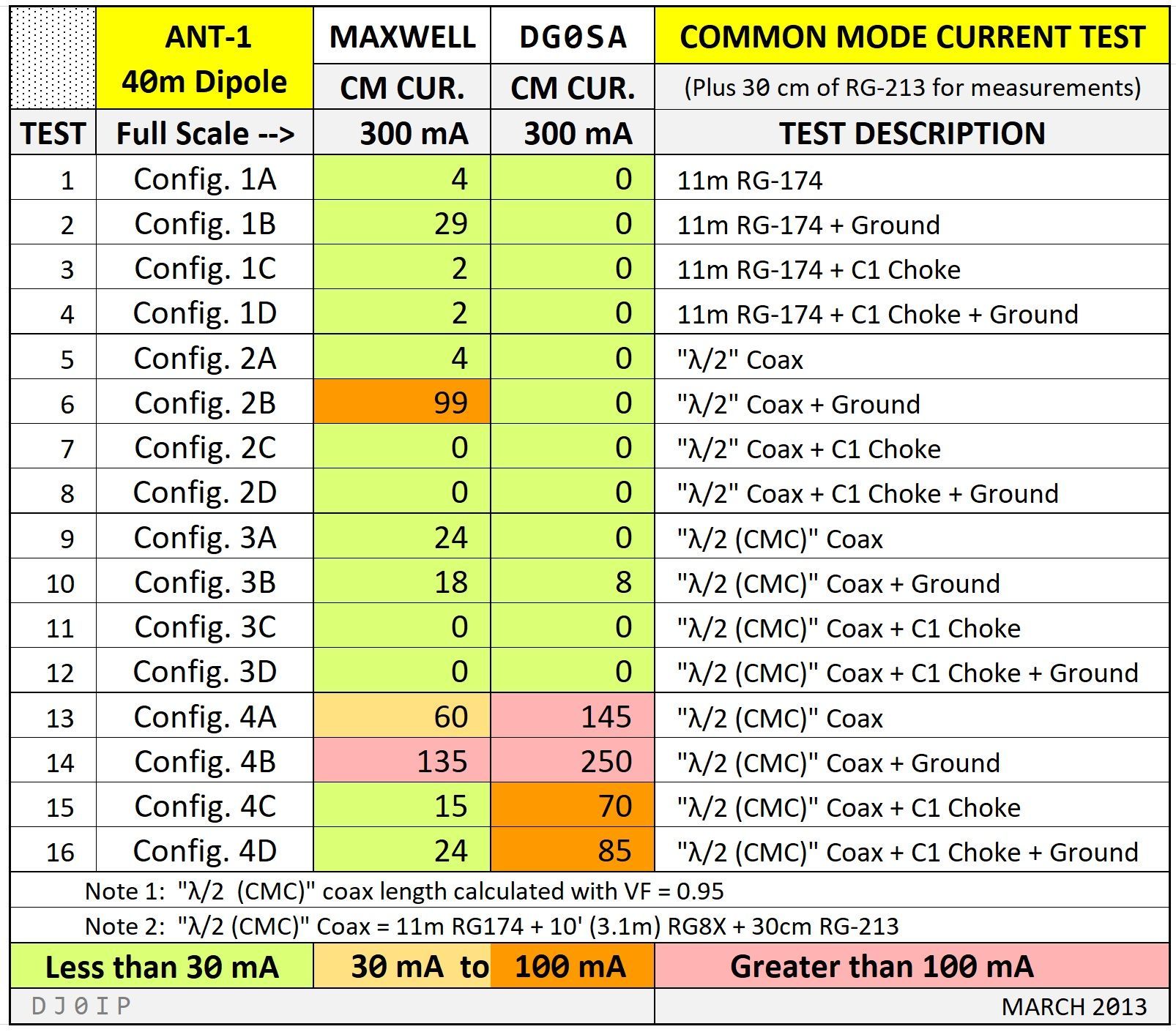
"Less than 30 mA of Common Mode Current" is the amount I determined to be safe, having no visible affect on the antenna's SWR curve.
The results were interesting, albeit a little confusing. For the first 12 tests, the DG0SA was clearly the superior balun. The Maxwell balun was still in the green area except for test #6 where it rose to 99 mA.
No surprise, when I skewed the coax for the last 4 tests, the Common Mode Current increased considerably with both baluns, but it was especially bad with the DG0SA balun!
THE BOTTOM LINE: Neither is a very good Choke-Balun!
As a result, I put the DG0SA balun into my junk box and never touched it again for 12 years.
As a result of the rest of the Common Mode Current Test, I determined what I thought to be the best balun for a 40m OCFD antenna: A Dual-Core 4:1 Guanella Balun.
Then I built an antenna with it to use for myself, naming it the Aerial-51 Model 404-UL.
One year later Spiderbeam began building and selling the antenna that I had designed. In the meantime, it has been reviewed in QST and RadCom and as of 2024, Spiderbeam has sold over 2000 of them world-wide.
Off Topic (but very important): I learned a lot about the Common Mode Current characteristics of the OCFD. Its biggest problem with Common Mode Current is on the fundamental band where it is often a magnitude stronger than on higher harmonic bands. The Common Mode Current degrades significantly on harmonic bands.
This means the CMI of the choke must be maximized for the fundamental band!
My Next Encounter with the DG0SA Choke - Balun . . . 12 Years Later:
Spiderbeam's customers loved my 404-UL and soon began asking for an 80m version of the antenna. I designed an 80m version of the 404-UL using the same dual-core 4:1 Guanella balun, but with additional turns of transmission line to improve 80m Common Mode Impedance. I also chose a different/better feedpoint position for it.
IT WAS A FLOP! TERRIBLE!
The problem was the balun. It had insufficient Common Mode Impedance, even with as many turns of coax as I could fit onto the two Toroid cores.
More research was needed. I planed an 80m OCFD Field Test similar to the one I had made when designing the 40m OCFD. I was assisted dearly by Steve Hunt, G3TXQ (SK), David Cutter, G3UNA, and Mel Farrer, K6KBE.
- Mel was one of the 3 founders of KLM Antennas. We had daily email contact during the 2 year long field test and when I encountered a couple of strange glitches, he replicated the antenna in California and confirmed them. We wanted to make sure it was not specific to my QTH.
- David collaborated with Ian White, GM3SEK, who gave us valuable information on preparing RF chokes for the D.C. and A.C. cables for the power supply, as well as tips for checking the calibration of the instruments I would be using.
- Steve was my coach in defining various positions along the coax to test at and in evaluating the hundreds of measurement I made.
Although I would be doing ALL of the work, building baluns and antennas, erecting them, testing them, etc., I felt like I was just
the waterboy for a team of professional engineers supporting me.
During my Battle of Baluns (BoB) Field Test, I tested 12 different balun, each with a much larger suite of tests than I had used in my 2013 Common Mode Current Field Test. Altogether it was about 500 tests. I assigned a name to each test and stored all of the data with local and cloud backups.
In the process of redefining the best balun to be used with an 80m OCFD antennas, I also learned several interesting and important things:
- Whenever Common Mode Current is present on the feedline, the feedline becomes part of the antenna, skewing several characteristics of the antenna.
- It causes the feedline to radiate all the way to the shack.
- It distorts the radiation pattern of the antenna.
- *MOST IMPORTANT: Common Mode Current skews the Frequency of Minimum SWR (SWRmin) and Resonance 'UP' in frequency on the fundamental band.
- The higher the Common Mode Current, the higher these two parameters are skewed up the band. (in ALL cases).
- The 80m OCFD requires a minimum of about 6k Ohm (based on the values shown in the G3TXQ color charts) of Common Mode Impedance to completely eliminate Common Mode Current from the feedline.
*Knowing this, it is easy to recognize when Common Mode Current is on the feedline, even when we do not have an RF Ammeter.
HERE is a sure way of testing an OCFD antenna for Common Mode Current:
- First erect the antenna as a center-fed dipole, fed with a good 1:1 current balun. The frequency of minimum SWR for an 80m OCFD should be about 40 kHz BELOW the band (i.e., 3.460 MHz).
- Measure the frequency at which minimum SWR (SWRmin) occurs and adjust the lengths for this frequency. Do not cut the ends of the wire, rather fold them back at the insulator and twist the excess wire back around itself, securing with a wire-tie.
- Once the lengths are adjusted, remove the balun and temporarily solder the two wires together.
- Cut the wire open at the position you wish to place the balun. I usually choose 29.7% from one end for my 80m OCFD antenna.
- Insert the balun to be used at this point.
- Measure SWRmin again and compare it to the SWRmin of the center-fed dipole (i.e., 3.460 MHz).
- If the frequency of SWRmin is more than about 5 kHz higher than the original frequency (i.e., 3.460 MHz), you have Common Mode Current on the feedline. You will need to add more choking (more Common Mode Impedance) to the feedpoint, or replace the balun with a better balun.
- If the frequency is +/- 5 kHz from the target frequency, you and no CM Current on the feedline, or it its level is so low that it is not noticeably affecting the antenna parameters.
NOTE: This procedure works EVERY TIME on an 80m OCFD antenna.
- I haven't tested it thoroughly on other antennas yet to see if it works on every antenna, every time.
Upon completing my Battle of Baluns Field Test, I created a chart showing where 80m SWRmin landed with the balun tested. In one of the tests, I then added a 1:1 W2DU (Maxwell) choke to the feedpoint to see if SWRmin moved. The choke had about 1k Ohm on 80m.
The Chart below shows my measured results, with and without the additional Maxwell choke. Originally I tested Baluns B1 thru B12 in 2015/2016. I added B13 (the DG0SA Choke-Balun) in 2024. It is a similar antenna, same design, but with thicker wire and erected in a different QTH. Thus the frequencies are slightly different.

As you can see in my chart, all of the hybrid baluns which I designed and built obtained an SWRmin within about 10 kHz of where it should be, based on my measurements made on the antenna as a simple center-fed dipole. All of these had about 8k Ohm of CMI.
NOTE: Each balun was measured on a different day. When measuring the same balun on different days, the frequencies sometimes varied by +/- 5 kHz.
- Whenever a balun had significantly less than 6k Ohm of CMI, the frequency of SWRmin rose, in a few cases quite a bit (i.e., B3, B5, B6, & B13).
- Inserting a Maxwell choke between these low-CMI baluns and the feedline resulted in SWRmin dropping quite a bit, for baluns which on their own had too high of an SWRmin (i.e., B3, B5, B6, & B13).
Notice the ones marked in RED. These had a CMI of 2k Ohm (either with or without the Maxwell choke). 2k Ohm CMI always resulted in SWRmin being at about 3.560 MHz.
Eight years later, I added “B13” to the bottom of the chart. This is the DG0SA choke-balun used in a hybrid balun together with the same 4:1 Ruthroff balun used in my own hybrid baluns.
NOTE: This is not the same identical antenna as used in my BoB test. It is the same design, but erected at a different location using a thicker antenna wire. Thus, frequencies can vary slightly, but not much.
The DG0SA choke used in the hybrid balun resulted in an SWRmin of 3.531 MHz. With the Maxwell choke inserted, SWRmin is at 3.490 MHz; better but still quite a way off from the antenna’s true SWRmin (which when tested with my standard hybrid balun is at 3.462 MHz.)
In order to estimate the real-life CMI of the DG0SA, I added several more Maxwell chokes, one at a time, measuring and recording SWRmin each time:

As you can see in the chart, each time I added an additional Maxwell choke, the frequency of SWRmin dropped, beginning with 3.531, then 3.490, 3.466, 3.458, and finally 3.447 MHz.
When adding the 5th Maxwell choke, SWRmin remained at 3.447 MHz (no change).
Thus, the DG0SA required 4 Maxwell chokes to reach the correct frequency of SWRmin. This equates to needing approximately an additional 4k Ohm of CMI, meaning the DG0SA used in this test had a CMI of about 2k Ohm.
CONCLUSION: a simple Guanella choke wound with 17 turns of coax onto an FT-140-43 has about 4x as much CMI as the DG0SA choke...AND is much easier to build.
This is not a model, nor a bogus lab measurement;
THIS IS REAL LIFE IN THE FIELD!
Maybe finished, but maybe still:

Rome wasn't destroyed in a single day!