THE COMPONENTS
PAGE CONTENTS:
1) 4:1 Ruthroff Baluns
2) 1:1 Guanella (Choke) Baluns
3) Accessories
4) The Antenna Analyzer
5) The Antenna
6) The Foolish Operator
7) Photo Gallery
1) 4:1 Ruthroff (voltage) Baluns
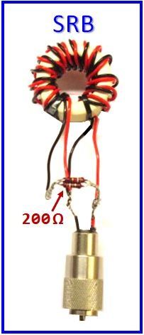
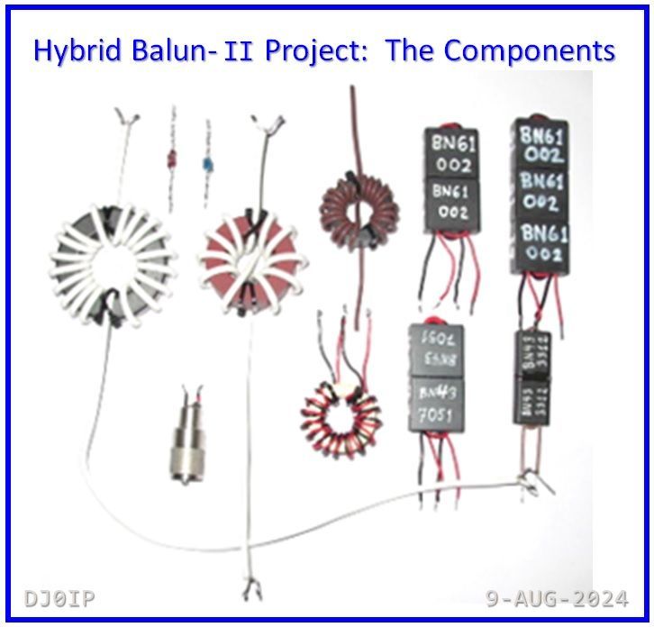
- SRB: Standard 4:1 Ruthroff (in the original Hybrid-Balun)
- 2B43jr: Dual-Binocular with tiny #43 Cores
- 2B43: Dual-Binocular with #43 Cores
- 2B61: Dual-Binocular with #61 Cores
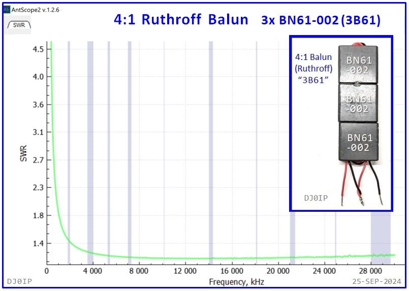
- 3B61: Triple-Binocular with #61 Cores

'Standard' Ruthroff Balun "SRB":
- 13 turns of Twisted-Pair, silver-plated solid copper wire, Teflon-Insulated
- Ferroxcube: FT-36-23-15-4C65 Toroid (~FT-140-61)
This is the balun used in my original 4:1 Hybrid-Balun for the Aerial-51 Model 807-xx 80m OCFD antenna.

'Dual-Binocular' #43 Ferrite "2B43Jr":
- 2 turns of RG-178 coax through a two Fair-Rite BN43-3312 Binoculars

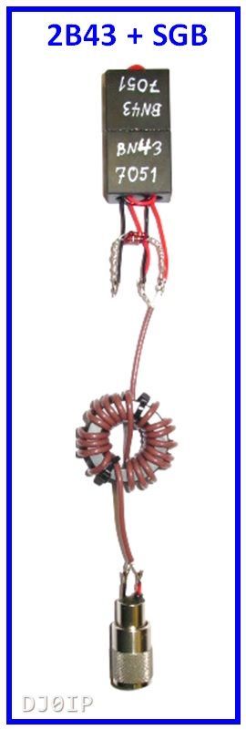
'Dual-Binocular' #43 Ferrite "2B43":
- 2 turns of Twisted-Pair wire through two Fair-Rite BN43-7051 Binoculars


'Dual-Binocular' #61 Ferrite 2B61:
- 2 turns of Twisted-Pair wire through two Fair-Rite BN61-002 Binoculars


'Triple Binocular' #61 Ferrite "3B61":
- 2 turns of Twisted-Pair wire through three Fair-Rite BN61-002 Binoculars.
2) 1:1 Guanella (current) Baluns
- SGB: Standard Guanella (choke) Balun used in my original Hybrid balun.
- HPFG: High-PWR Guanella (choke) Balun
- HPVG: High-PWR Vitroperm Guanella
- DG0SA: Dual 100 Ohm Transmission Lines connected in parallel.

'Standard' Guanella Balun "SGB":
- 19 turns of RG-316, Teflon-insulated coax
- Ferroxcube: FT-36-23-15-3S4 Toroid (~FT-140-43)
This is the balun used in my original 4:1 Hybrid-Balun for the Aerial-51 Model 807-xx 80m OCFD antenna.
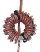

'High-Power' Ferrite Guanella Balun (#43), "HPFG":
- 19 turns of DXW-50, Teflon-insulated coax
- On an Amidon FT-240-43
This is the choke used in the high power version of my original Hybrid-Balun.


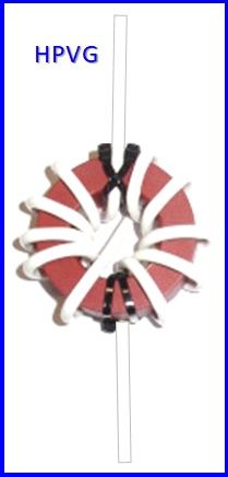
'High-Power' Vitroperm Guanella Balun, "HPVG":
- 11 turns of DXW-50, Teflon-insulated coax
- Vitroperm Toroid: T6006-L2045-V102
This is the balun with a Toroid using a non-ferrite core.

'Dual 100 Ohm Transmission Line" Choke-Balun "DG0SA":
- 2x 12 turns of 100-Ohm bifilar windings (one on each side) The windings are wired in parallel presenting a good 50 Ohm impedance.
- Wurth RK3 Ferrite Toroid, Permeability 620. It's diameter is 40 mm.
Lots of members of various online balun and antenna groups praise this balun as if it were the greatest thing since sliced bread. Its lab tests look good indeed, having broadband low SWR and Common Mode rejection tests (in the lab) look very good.
But . . . in my 2013 Common Mode Current Field test, I tested one of these and it flopped in the field.
The problem with this design is, each transmission line can only occupy half the space of the Toroid. This limits the number of turns that can fit in each half of the balun.
How well does it work as a choke in a Hybrid-Balun?


3) ACCESSORIES
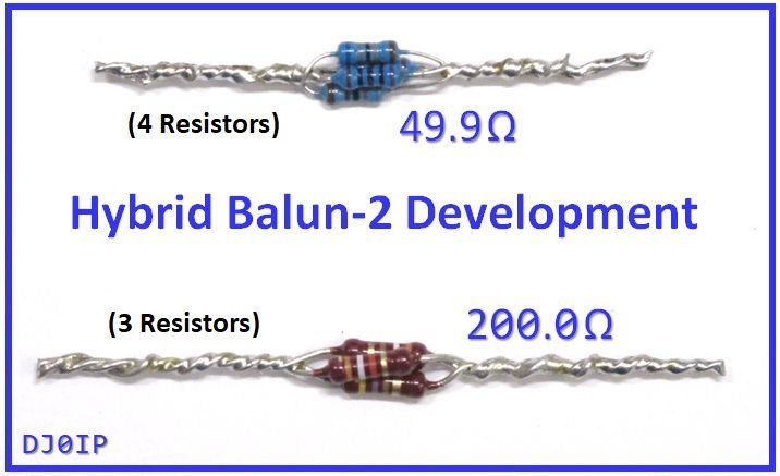
- 50 Ohm (49.9 Ω) Dummy Load
- Home-Brew
- 200 Ohm (200.0 Ω) Dummy Load
- Homebrew
- PL-259 with wire connections
(Dummies were made by paralleling multiple resistors together.)

4) THE ANTENNA ANALYZER
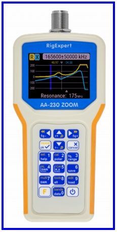
The Antenna Analyzer is a RigExpert AA-230 ZOOM
- Frequency Range: 0 - 230 MHz
- BlueTooth Enabled
The FreeWare Software App used to view the measurement files is "AntScope-2", and can be downloaded here:
5) THE 80m OCFD ANTENNA
- Design:
- Aerial-51 "807-HD"
- Coax:
- elect. ½ λ RG-58 CU
- Configuration:
- Inverted-V
- Feedpoint: 29.7%
- AGL: 5m/13m/6m
The red thing in the long leg of the antenna raises the resonance on 80m.
The drawing is NOT to scale ->

This antenna is currently built and sold by Spiderbeam, World-Wide. With over 300 of these antennas in the field, we are well aware of its characteristics and performance. In this test we will test different baluns and compare the results to the existing knowledge of this antenna.
NOTE: We will leave that
"RED Thing" out for all of our field tests. As a result, the frequency of minimum SWR on 80m will always be about 50 kHz below the bottom of the band. We can later insert that red thing and raise 80m resonance to any place within the band we want it.
If you are interested in learning about that antenna, see: Aerial-51 Model 807-HD
6) THE CRAZY OPERATOR
- Name: Rick Westerman
- (BlueTooth - Enabled)
- Call Signs: DJ0IP / NJ0IP / G5BMH
- AGE: 76 (in 2024)
- First Licensed: WN5ETA in 1962
- In Germany: DA2QC in 1972
- In the U.K.: G5BMH in 1975
- SWL: (U.K.) ISWL 10006 in 1960

7) PHOTO GALLERY
NOTE: Throughout this section of my web, whenever I state the value of the Common Mode Impedance of chokes or balun, it is based on the values shown in the color charts by Steve Hunt, G3TXQ (SK), published on his web, here: G3TXQ: RF-Chokes


